


 Language


Ruilin PPTC Protection for USB Type-C
USB Type-C has become the standard connector for smartphones, tablets, laptops, industrial equipment, consumer electronics, docking stations and many other electronic products. Its reversible connector and support for higher power levels make USB-C convenient, but they also introduce additional circuit-protection requirements.
A reliable USB-C port may need protection against overcurrent, short circuits, ESD, overvoltage and accidental VBUS faults. These protection functions are normally handled by different components rather than by a single device.
A PPTC resettable fuse is particularly useful for protecting the USB-C power path, especially the VBUS line, against excessive current and sustained short-circuit conditions.
This article explains how PPTC protection can be used in USB Type-C designs, what the CC pins do, and how USB-C overcurrent protection differs from ESD protection.
1. Why Does USB Type-C Need Circuit Protection?
USB Type-C combines power delivery and high-speed data communication in a compact connector. The USB Type-C connector includes VBUS power pins, ground, USB data lines, high-speed TX/RX lines, CC1/CC2 configuration-channel pins and SBU pins for supported alternate functions.
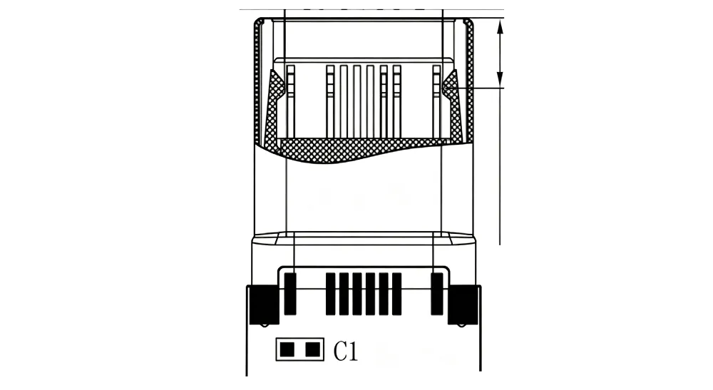
The compact connector geometry also means that protection cannot be considered only from the perspective of the power supply.
Typical USB-C fault conditions include:
VBUS overcurrent
VBUS short circuit
Excessive current caused by a damaged peripheral
ESD when a user inserts or removes a cable
Accidental shorting between CC and VBUS
Overvoltage on CC or SBU lines
Faults caused by non-compliant cables or accessories
Therefore, a practical USB-C protection design normally separates the protection requirements into several areas:
| Protection requirement | Typical protection device |
|---|---|
| VBUS overcurrent | PPTC resettable fuse / current-limit IC |
| VBUS short circuit | PPTC / power protection IC |
| ESD on data lines | TVS / ESD protection device |
| ESD on CC/SBU | TVS / dedicated USB-C protection IC |
| CC-to-VBUS fault | USB-C protection IC |
| VBUS overvoltage | OVP / power protection IC |
This distinction is important: PPTC is primarily an overcurrent and short-circuit protection component, not an ESD protection device.
2. How Does a PPTC Protect a USB-C Port?
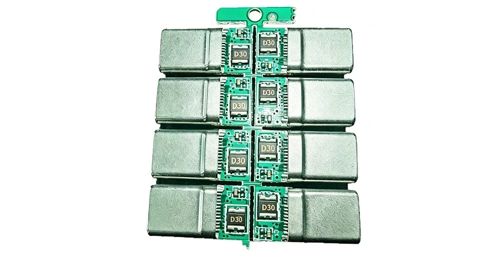
A PPTC, also called a polymeric positive temperature coefficient resettable fuse, is normally connected in series with the protected power path.
For a USB-C power input, a simplified protection structure can be represented as:
USB-C VBUS → PPTC → Power Management Circuit → System Load
Under normal operating conditions, the PPTC has relatively low resistance and allows the required operating current to pass.
When an abnormal overcurrent or short-circuit condition occurs, the PPTC heats up. Its resistance increases significantly, limiting the current flowing through the protected circuit.
Once the fault is removed and the PPTC cools down, its resistance decreases and the device can return to normal operation.
This makes a PPTC particularly attractive for equipment where replacing a conventional fuse after every fault is undesirable.
Typical USB-C PPTC protection sequence
Normal operation
VBUS → PPTC → Load
Overcurrent
VBUS → PPTC heats → Resistance increases → Current is limited
Fault removed
PPTC cools → Resistance decreases → Normal operation resumes
The actual protection behavior depends on the PPTC's electrical characteristics, ambient temperature, PCB layout and fault conditions. Designers should therefore select the device using the manufacturer's datasheet rather than choosing a part only from its nominal current rating.
3. Where Should the PPTC Be Placed in a USB-C Circuit?
For applications where USB-C is used as a power input, the PPTC is commonly placed in series with the VBUS power path.
A simplified circuit is:
USB-C VBUS → PPTC → DC/DC Converter / PMIC → System
The objective is to prevent excessive current caused by a downstream fault from continuously flowing through the connector, PCB traces and power-management circuitry.
For a USB-C power output or source application, the protection architecture may be different. A dedicated power-path protection IC or current-limiting switch may be used together with other protection components.
The correct solution depends on whether the USB-C port functions as a:
Sink
Source
Dual-Role Power (DRP) port
USB data port
USB-C charging port
USB-PD port
4. Does USB-C Have Overcurrent Protection?
USB-C itself does not automatically mean that the system has complete overcurrent protection.
The USB Type-C specification defines the connector and interface behavior, while the actual system implementation determines how overcurrent and other fault conditions are handled.
For example, USB-C source designs can use dedicated protection circuitry to provide VBUS overcurrent protection. STMicroelectronics describes USB-C source and dual-role applications where overcurrent protection is required on the VBUS path.
Depending on the design, overcurrent protection can be implemented using:
PPTC resettable fuses
Current-limiting switches
USB-C protection ICs
Power-path controllers
eFuse devices
MOSFET-based protection circuits
A PPTC is attractive when the design requires a simple, passive and resettable overcurrent protection solution.
However, if the application requires accurate current limiting, fast electronic shutdown, power-path control or detailed USB-PD fault management, a dedicated protection IC may be more appropriate.
5. How to Protect Your USB-C Port?
A complete USB-C protection strategy normally uses several layers.
Layer 1: VBUS Overcurrent Protection
Use aPPTC resettable fusein series with the VBUS path to limit excessive current caused by a downstream short or overload.
Layer 2: ESD Protection
Use suitable ESD/TVS protection for USB-C signal and interface pins where required.
ESD is particularly important because the connector is frequently exposed to direct user contact. USB Type-C protection references from major semiconductor manufacturers include dedicated IEC 61000-4-2 ESD protection for CC and other USB-C interface pins.
Layer 3: CC Protection
CC1 and CC2 need special consideration because they are located close to VBUS and are used for configuration and connection management.
Dedicated USB-C protection ICs can provide overvoltage protection when CC pins are exposed to a VBUS fault.
Layer 4: VBUS Overvoltage Protection
For USB-C PD applications, the power system can operate at significantly higher VBUS voltages than traditional 5 V USB applications.
Therefore, designers may need OVP and other power-path protection in addition to overcurrent protection.
Layer 5: System-Level Protection
The protection design should also consider:
PCB trace current capability
Connector rating
Operating temperature
Cable characteristics
USB-PD operating voltage
Maximum continuous load current
Fault current
Required interruption time
Required reset behavior
A PPTC should therefore be regarded as one part of the USB-C protection architecture, rather than a replacement for every other protection component.
6. Does USB Need ESD Protection?
Yes, USB interfaces generally require careful consideration of ESD protection, especially externally accessible USB ports.
USB-C connectors are directly exposed to cable insertion, removal and user contact. An ESD event can couple transient energy into sensitive USB transceiver, controller and power-management circuitry.
However,PPTC and ESD protection serve different purposes.
A PPTC responds primarily to excessive current and heating over a longer fault interval.
An ESD protection device is designed to respond to very fast transient events and clamp the voltage to protect sensitive semiconductor devices.
Therefore:
PPTC ≠ ESD protection
A typical design may use:
USB-C connector → ESD/TVS protection on signal lines
and
USB-C VBUS → PPTC → power circuit
This combination addresses two different classes of electrical faults.
7. What Are CC Pins on USB-C?
The CC pins are Configuration Channel pins, called CC1 and CC2.
They are a distinctive part of the USB Type-C interface and are used to establish and manage the connection between a USB-C source and sink. They also participate in cable orientation detection and current advertisement/configuration.
The USB Type-C connector uses two CC pins because the connector is reversible. Depending on how the plug is inserted, one of the CC pins becomes the active configuration channel.
CC pins can be involved in:
Cable attachment detection
Plug orientation detection
Source/sink identification
Current capability advertisement
USB Power Delivery communication
VCONN-related functions in applicable configurations
Because CC pins are physically close to VBUS, they can also be exposed to abnormal voltage conditions. Dedicated USB-C protection devices are available specifically to protect CC1/CC2 against short-to-VBUS and ESD events.
This is another reason why a PPTC placed on VBUS should not be considered a complete CC protection solution.
8. PPTC vs. USB-C Protection IC
The choice between a PPTC and a dedicated USB-C protection IC depends on the protection requirement.
| Feature | PPTC Resettable Fuse | USB-C Protection IC |
|---|---|---|
| Overcurrent protection | Yes | Yes |
| Short-circuit protection | Yes | Yes |
| Resettable | Yes | Usually automatic |
| ESD protection | No | Some devices integrate ESD |
| CC protection | No | Yes, depending on device |
| VBUS overvoltage protection | No | Yes, depending on device |
| Power-path control | No | Yes |
| Current sensing | No | Some devices |
| Circuit complexity | Low | Higher |
| Passive protection | Yes | No |
| Cost-sensitive designs | Excellent | Depends on application |
For a simple USB-C power-input design, a PPTC can provide a cost-effective first layer of overcurrent protection.
For USB-C PD, high-power applications or designs requiring precise electronic control, a dedicated protection IC may be used in addition to—or instead of—a PPTC.
9. How to Select a PPTC for USB-C Protection
Selecting a PPTC based only on the USB-C nominal current is not sufficient.
The following parameters should be considered.
9.1 Hold Current — Ihold
Ihold is the maximum current that the PPTC can carry under specified conditions without entering its tripped state.
The selected Ihold should be higher than the application's normal continuous operating current.
9.2 Trip Current — Itrip
Itrip is the current at which the PPTC is expected to enter its high-resistance protection state under specified test conditions.
A suitable design should ensure that the PPTC can respond to the expected fault current.
9.3 Maximum Voltage
The PPTC's maximum operating voltage must be compatible with the actual USB-C VBUS application.
This is particularly important for USB-C Power Delivery applications.
9.4 Maximum Fault Current
The designer should verify the maximum fault current and the PPTC's interrupt/fault-handling capability under the actual circuit conditions.
9.5 Initial Resistance
The PPTC's initial resistance directly affects voltage drop and power dissipation.
For higher-current USB-C applications, low initial resistance becomes increasingly important.
9.6 Temperature Derating
PPTC characteristics are temperature dependent.
A part that works correctly at 25°C may behave differently at elevated ambient temperatures.
Therefore, Ihold and Itrip should always be evaluated against the actual operating temperature range.
10. PPTC Protection for USB-C Charging Applications
USB-C charging applications are one of the most relevant use cases for PPTC protection.
Examples include:
USB-C wall chargers
Power banks
Portable electronics
Industrial handheld terminals
Smart home devices
Embedded controllers
Consumer electronics
USB-C hubs
Docking stations
Battery-powered equipment
For these products, the PPTC can provide an additional protection layer against abnormal current conditions on the power path.
A typical architecture may include:
USB-C Connector-ESD / TVS Protection-PPTC Resettable Fuse on VBUS-OVP / Power Protection-DC/DC Converter or PMIC-System Load
The exact architecture depends on whether the USB-C port is configured as a source, sink or dual-role port.
11. Why Use a PPTC Instead of a Conventional Fuse?
A conventional fuse normally needs to be replaced after it operates.
A PPTC resettable fuse can return toward its low-resistance state after the fault has been removed and the device has cooled.
This provides several advantages for USB-C products:
No fuse replacement after a temporary fault
Compact PCB implementation
Simple passive protection
Automatic reset
Low external component count
Suitable for mass-produced consumer electronics
Useful for protection against sustained overcurrent and short circuits
However, PPTC protection is not instantaneous in the same way as an electronic protection switch or transient clamp. Its response depends on the device characteristics and fault conditions.
For this reason, the PPTC should be selected according to the actual protection objective.
12. Design Considerations for USB-C PPTC Protection
When designing a USB-C circuit, engineers should evaluate the entire protection path rather than selecting a component independently.
Important questions include:
What is the maximum continuous VBUS current?
Is the port a source, sink or DRP?
Does the application support USB Power Delivery?
What is the maximum VBUS voltage?
What is the expected short-circuit current?
What ambient temperature range must the product support?
Is ESD protection required on CC, D+/D-, SBU and high-speed lines?
Is CC-to-VBUS short protection required?
What voltage drop can the system tolerate?
Is automatic reset required?
These factors determine whether the optimal solution is a PPTC alone or a combination of PPTC, TVS/ESD protection and a dedicated USB-C protection IC.
13. PPTC Protection for USB Type-C: Key Takeaways
USB Type-C provides significant advantages in power delivery, connectivity and connector usability, but its compact and multifunctional interface requires a well-designed protection strategy.
The key points are:
PPTC can provide resettable overcurrent protection on the USB-C VBUS power path.
PPTC is not an ESD protection device.
USB-C ports may require dedicated ESD/TVS protection.
CC1 and CC2 are Configuration Channel pins used for connection and configuration functions.
CC pins may require dedicated protection against ESD and short-to-VBUS conditions.
USB-C overcurrent protection is determined by the system implementation, not simply by having a Type-C connector.
USB-C PD applications require careful consideration of voltage, current and protection ratings.
PPTC selection should consider Ihold, Itrip, resistance, voltage, temperature and fault conditions.
For cost-sensitive USB-C products requiring simple and resettable power-path protection, a properly selected PPTC can be an effective component within a multi-layer protection strategy.
FAQs
How to protect your USB-C port?
A USB-C port generally requires different types of protection for different fault conditions. A typical design can use a PPTC resettable fuse for VBUS overcurrent protection, ESD/TVS devices for transient protection, and a dedicated USB-C protection IC where CC, SBU or VBUS overvoltage protection is required.
Does USB need ESD protection?
Yes. Externally accessible USB ports are exposed to electrostatic discharge from users and cables. ESD protection is normally implemented using dedicated ESD/TVS protection devices or integrated protection ICs. A PPTC should not be used as a substitute for ESD protection.
Does USB-C have overcurrent protection?
USB-C itself does not guarantee complete system-level overcurrent protection. The product designer must implement the appropriate protection circuitry. Depending on the application, this may include a PPTC, current-limiting switch, eFuse, power-path controller or USB-C protection IC.
What are CC pins on USB-C?
CC1 and CC2 are Configuration Channel pins in the USB Type-C interface. They are used for connection detection, plug orientation, source/sink configuration and related USB-C functions. They also play an important role in USB Power Delivery communication.
Can a PPTC protect USB-C from ESD?
No. A PPTC is designed primarily for overcurrent and sustained fault protection. ESD is a very fast transient event and normally requires dedicated ESD/TVS protection.
Where should a PPTC be installed in a USB-C circuit?
For USB-C power-path protection, the PPTC is normally connected in series with the VBUS path. The exact location depends on the system architecture and whether the USB-C port functions as a source, sink or dual-role port.
Is a PPTC suitable for USB-C Power Delivery?
It can be, provided that the selected PPTC is rated for the application's voltage, current, temperature and fault conditions. USB-C PD applications require particular attention to VBUS voltage and current because the power level can be significantly higher than traditional USB applications.
What is the difference between PPTC and TVS protection for USB-C?
A PPTC primarily limits excessive current and protects against sustained overcurrent or short-circuit conditions. A TVS/ESD device clamps fast transient voltages such as ESD. They protect against different failure mechanisms and can be used together.
How do I choose a PPTC for USB-C?
Start with the normal operating current and maximum VBUS voltage, then evaluate Ihold, Itrip, initial resistance, temperature derating, fault current and required voltage drop. Always verify the selected part using the manufacturer's datasheet and application conditions.
About Ruilin Semiconductor
Ruilin Semiconductor (Shenzhen) Co., Ltd.is a semiconductor and circuit-protection component manufacturer focused on reliable protection solutions for electronic applications.
Ruilin Semiconductor develops and manufactures PPTC resettable fuses for applications including USB interfaces, consumer electronics, industrial equipment, automotive electronics, power supplies, battery-powered products and other electronic systems.
Our PPTC product portfolio covers different package sizes, voltage ratings and current ranges to help engineers select suitable resettable overcurrent protection for their designs.
For USB Type-C applications, Ruilin Semiconductor provides PPTC solutions for VBUS overcurrent and short-circuit protection, helping customers build compact, resettable and cost-effective power protection circuits.
For detailed electrical specifications, including Ihold, Itrip, resistance, voltage rating, trip time and temperature characteristics, engineers should refer to the corresponding Ruilin Semiconductor PPTC datasheet.
Ruilin Semiconductor — PPTC Resettable Fuse Manufacturer for Reliable Circuit Protection.